コレクション: バンドパスフィルタ

バンドパス フィルターは、特定の範囲の波長を通過させ、他の波長をブロックするコンポーネントです。マシン ビジョン、ライダー、蛍光、分光法、天文学、太陽シミュレーションで広く使用されています。

Bandpass Filter Banner

Basic Specifications

You can search BP[CWL]-[FWHM] to find the Bandpass Filter directly.

BP266-10 = Bandpass Filter with Center Wavelength=266nm, FWHM=10nm

  • 中心波長(CWL)

    CWL は中心波長の略です。これは、フィルタの通過帯域の中間点に位置する特定の波長を指します。これは、フィルタが他の波長をブロックしながら透過を許可する波長の範囲です。CWL は、指定された帯域幅内で最大の透過が発生する場所を示すため、フィルタのパフォーマンスを決定する重要なパラメータです。

  • FWHM (帯域幅)

    半値全幅 (FWHM) は、光バンドパス フィルターの特性評価において重要なパラメーターです。これは、フィルターの通過帯域の幅を、最大透過率の半分で定義します。

  • ピーク透過率 (Tpk)

    ピーク透過率 (Tpk) は、光バンドパス フィルターの重要な仕様です。これは、通常、中心波長 (CWL)またはその付近にある最も効果的な波長でフィルターを通過できる光の最大パーセンテージを表します。

  • ブロック領域

    ブロッキング領域はブロッキング バンドまたはストップバンドとも呼ばれ、光フィルタが効果的に減衰または完全にブロックする波長または周波数の範囲を指します。この領域は、さまざまな光学アプリケーションで不要な光が目的の信号に干渉しないようにするために重要です。

  • 光学密度

    光学密度 (OD) は、物質を通過する際に光がどの程度吸収または遮断されるかを示す指標です。光の減衰を定量化し、数学的には入射光強度と透過光強度の比の対数 (底 10) として定義されます。

折りたたみ可能なコンテンツ

UV Range Bandpass Filter usually have lower transmission

The transmittance of UV bandpass filters generally falls between 15-30%.This relatively low transmission is inherent to UV filter design and materials.

Limiting Factors

Several factors contribute to the lower transmission rates:

Material Limitations

  • Most materials used in UV filters have inherent absorption in the UV range
  • The absorption of UV light by materials makes it difficult to achieve high transmission while maintaining deep blocking over wide wavelength ranges

Design Challenges

  • The refractive index difference of dielectric materials decreases at shorter wavelengths, requiring more layers to achieve desired spectral control.
  • Complex designs with multiple layers are needed for effective UV filtering, which can increase optical scatter and reduce transmission.

Infrared (IR) range Bandpass filter are more costly

Cost Factors

IR bandpass filters are indeed typically more expensive than visible and NIR counterparts due to:

  • Limited material choices suitable for IR wavelengths
  • More complex fabrication processes

Substrate Materials for IR range

Germanium (Ge)

  • Excellent transmission properties in MWIR to FIR ranges
  • Particularly effective for wavelengths from 1.7 µm and longer
  • Features high refractive index and high Knoop hardness
  • Ideal for thermal imaging and rugged IR imaging applications

Silicon (Si)

  • Cost-effective solution for IR applications
  • Transmission starts from approximately 1.2 µm
  • Lightweight material with good performance
  • Commonly used in spectroscopy, MWIR laser systems, and THz imaging

Sapphire (Al₂O₃)

  • Known for exceptional durability and scratch resistance
  • Provides broad transmission capabilities
  • Particularly effective in NIR applications
  • Used in IR laser systems, spectroscopy, and rugged environmental equipment

Using Condition

Different using condition may result in spectral characteristic changes.

  • Angle of Incidence

    When increasing the Angle of Incidence (AOI) in a Bandpass Filter.

    The most significant change is the Spectral Shift, where the transmission spectrum shifts toward shorter wavelengths as the AOI increases.

  • Temperature Effects

    Most filters show a red shift (shift to longer wavelengths) with increasing temperature.

    And filter will have blue shift (shit to shorter wavelength) with decreasing temperature.

Spectral Features

Spectral performance is decided by the coating design,substrate selection and coating machine.

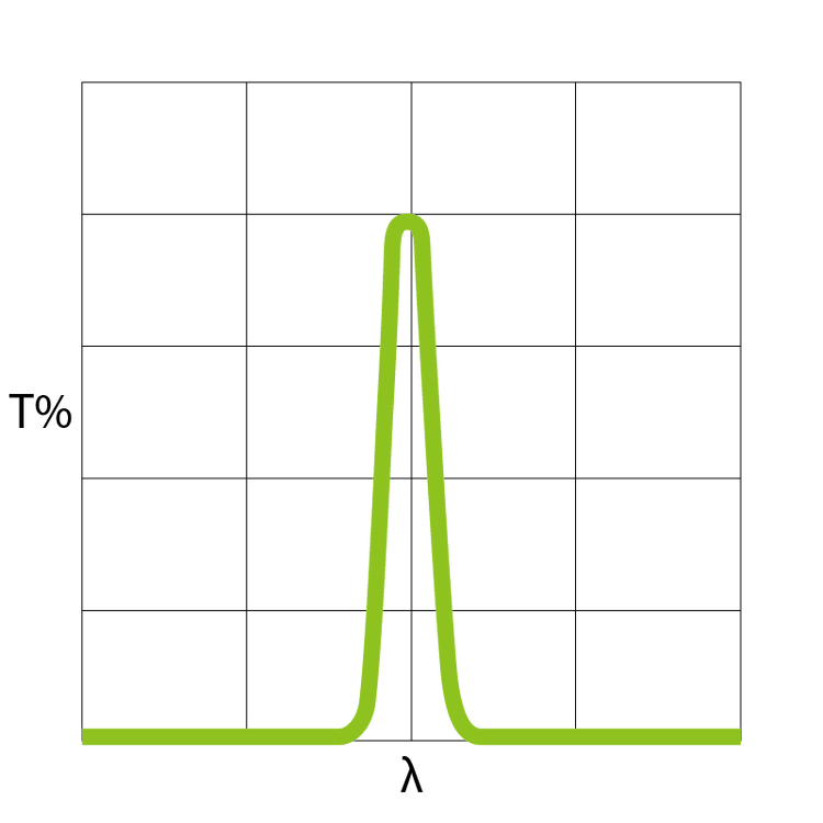
  • Gaussian Type Bandpass Filter

    The Gaussian type bandpass filter creates a bell-shaped (Gaussian) transmission curve.

    Commonly used in

    • LED-based systems
    • Cost sensitive solution
  • Flat-Top Bandpass Filter

    A flat-top type Bandpass Filter provides consistent light transmission across a specific wavelength range.

    Commonly used in

    • Laser-based remote sensing
    • Where AOI may slightly changes

折りたたみ可能なコンテンツ

Why Flat-Top spectral is needed in LiDAR system?

Footprint Elongation

The laser footprint becomes elongated due to:

  • Changes in scan angle during flight
  • Variations in terrain slope
  • Combined effects of both factors affecting the AOI

When an optical interference filter is tilted from normal:

  • The transmission spectrum experiences a "blue shift" toward shorter wavelengths
  • The shift becomes more pronounced with increasing AOI
  • The flat-top design provides a wider tolerance window for these shifts

Bandpass Filter Construction

  • Laminate Filter

    Multiple Filters bonded together

    • Protected by sealing and ring assemblies
    • Often mounted in protective housing

    CONS of Laminate Filter

    • Low Durability
    • Moderate Spectral Performance
    • Ghost Image may occur

  • Hard Coating Filter

    Hard coated filters are manufactured using plasma deposition processes with computer-controlled precision

    • Even layer distribution
    • Superior environmental durability

    CONS of Hard Coating Filter

    • Expensive
    • Less Flexible Combination

Moutning Solution

  • Unmounted

    Unmounted optical filters are typically packaged as a sandwich structure with protective films on both sides, then wrapped in foam or bubble wrap for additional protection during shipping and storage.

  • Threaded Mounting

    Threaded mounting is a mechanical method for securely attaching optical filters to lenses or equipment using standardized threaded rings.

  • Filter Wheel

    A filter wheel is a rotatable mechanical device designed to hold multiple optical filters and sequentially select them into the light path.

  • Fiber Optic Filter Muont

    A fiber optic filter mount is a specialized optical device designed to integrate filters and other optical components into fiber-based light paths.

  • Filter Cube

    A filter cube is a specialized optical assembly used primarily in fluorescence microscopy to control and manipulate specific wavelengths of light.

  • Customized Structure

    We offer custom optomechanical design and fabrication services from your 3D drawings, with prototype builds starting at $150.

    • MOQ start from 1 unit

Services

  • Dicing

    We provide dicing services to cut larger filters into smaller piece.

    Example:

    • Dia100mm (1pcs) -> 10x10mm (40pcs)
    • Price = 50USD
    • When order in larger quantity (and customization), dicing service is free.

  • Transmission Inspection

    We use Cary Spectrophotometer for bandpass filter inspection. You can request raw data from us before ordering.

    • Request existing testing data is free
    • Extra transmission testing will cost $35 per sample

    >> sample data.csv

折りたたみ可能なコンテンツ

Optical FIlter usually produced in a large wafer

  • Filters are typically produced as large plates (up to 12" diameter) with coatings applied first
  • The coated plates are then cut into desired dimensions using various methods:
  1. Dicing with ultra-thin blades for precise cuts
  2. CNC sawing for squares and rectangles
  3. Diamond core drilling for circular shapes

The large-plate approach for filters offers several advantages:

  • Multiple filters can be produced from a single coated plate
  • Reduces overall production time compared to individual processing
  • Allows for better quality control of coating uniformity

Bandpass Filter Directory

Customization

We provide bandpass filter customization service for small and large scale project.

  • What you need to know before customization

    • Minimum Order Quantity depends on the Coating Chamber size.
    • Require quantity less than the minimum yield won't lower the price a lot.
    • Minimum Cost will start from 1,500$ per chamber coating.
    • Leadtime will be usually within 2-6 weeks
  • Customization Range

    Below are the specification we can achieve. (But not together on one product)

    • Center Wavelength = 220nm - 10500nm
    • Minimum FWHM = 0.8nm
    • Optical Density = OD6

お問い合わせフォーム